The core of selecting insert geometry is to align with the specific requirements of the machining operation. Different processes have distinct demands for cutting angles and chip evacuation designs. For example, in finishing applications, geometries with sharp cutting edges and smooth chip flow should be chosen to prevent chips from scratching the machined surface. In roughing, prioritize geometric designs with strong impact resistance to handle complex forces under heavy cutting loads. Additionally, the material being machined influences geometry selection—for soft materials, focus on chip evacuation efficiency; for hard materials, enhance cutting edge strength.
1. Insert Geometry: Precisely Match the Machining Operation
The core of selecting insert geometry is to align with the specific requirements of the machining operation. Different processes have distinct demands for cutting angles and chip evacuation designs. For example, in finishing applications, geometries with sharp cutting edges and smooth chip flow should be chosen to prevent chips from scratching the machined surface. In roughing, prioritize geometric designs with strong impact resistance to handle complex forces under heavy cutting loads. Additionally, the material being machined influences geometry selection—for soft materials, focus on chip evacuation efficiency; for hard materials, enhance cutting edge strength.
2. Insert Grade: Adapt to Material Characteristics

Insert grade determines wear resistance, heat resistance, and impact resistance, and must be selected based on the hardness and toughness of the workpiece material. For instance, universal carbide grades work well for machining ordinary carbon steel and alloy steel. For difficult-to-cut materials like high-temperature alloys and stainless steel, high-performance grades with high cobalt content or special coatings are required to ensure stable cutting performance under high-temperature and high-pressure conditions. Choosing the right grade can extend insert service life by over 30% and reduce replacement frequency.
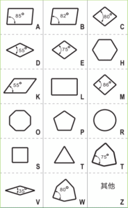
3. Insert Shape (Nose Angle): Balance Strength and Machining Range
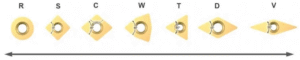
Nose angle is a core indicator of insert shape, and the selection follows the basic principle of “larger = stronger.” A larger nose angle enhances overall insert strength, distributes cutting pressure, and reduces the risk of edge chipping—ideal for roughing with large depths of cut and high feed rates, balancing strength and cost-effectiveness. However, it’s important to note that a larger nose angle imposes stricter limits on the internal contour radius of the workpiece. For machining complex contours such as small arcs and narrow grooves, inserts with corresponding small nose angles are necessary to ensure machining precision.
4. Insert Size: Scientifically Match the Depth of Cut
Insert size should directly correspond to the machining depth, avoiding “over-sizing” or “under-sizing.” For large depths of cut, select larger inserts to ensure sufficient cutting edge length to withstand cutting loads and prevent deformation from excessive force. For small depths of cut, smaller inserts can be used to reduce the contact area between the tool and workpiece, improving cutting flexibility—especially suitable for finishing or thin-walled parts machining to minimize workpiece deformation. Additionally, insert size must match the tool holder specifications for secure installation.
5. Nose Radius: Balance Strength and Machining Quality

Nose radius selection requires balancing insert strength and workpiece quality. Prioritize a larger nose radius to enhance cutting edge impact resistance, reduce tip wear, extend service life, and improve cutting stability—ideal for high-feed machining. However, if vibration occurs during machining, switch to a smaller nose radius promptly. A small nose radius reduces cutting resistance and vibration amplitude, making it suitable for machining vibration-prone workpieces such as slender shafts and thin-walled parts, ensuring meeting surface roughness requirements.
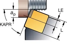
6. Entering Angle (Lead Angle): Optimize Cutting Forces and Chip Evacuation
The entering angle directly affects cutting force distribution and chip flow direction, serving as a key parameter for improving machining efficiency. A reasonable entering angle distributes cutting forces across multiple insert edges, avoiding excessive local stress, while guiding chips to flow in a preset direction to prevent wrapping around the workpiece or scratching the machined surface. For example, when machining shafts, an appropriate entering angle can reduce radial cutting forces to avoid workpiece bending. When machining end faces, adjusting the entering angle improves cutting smoothness and reduces built-up edge formation.