

Description
Introduction:
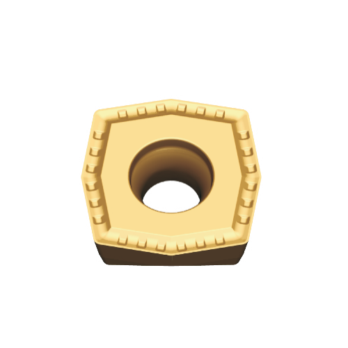
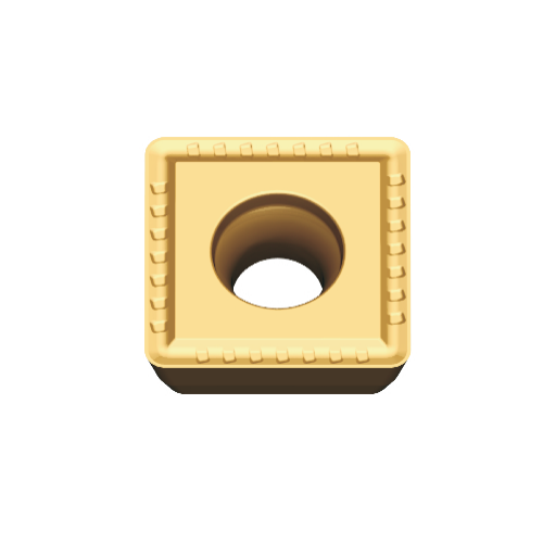
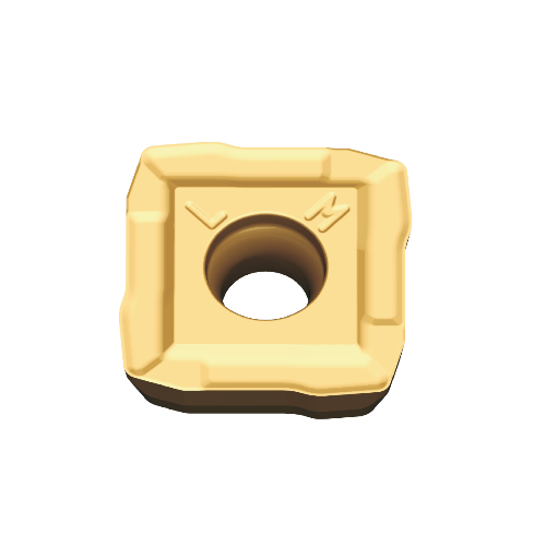
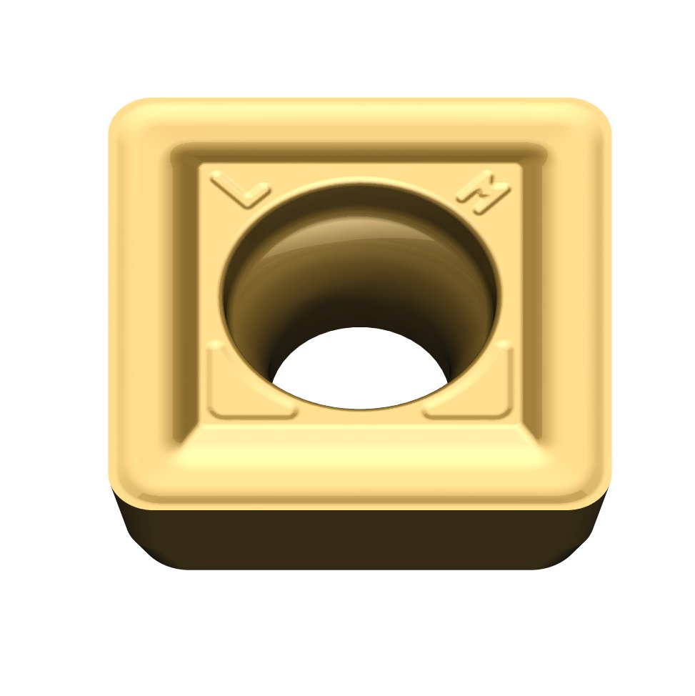
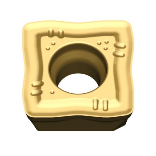
The ZCMT-BM Drilling Insert is a precision indexable carbide insert developed for high-efficiency holemaking in modern CNC machining environments. Its geometry integrates a positive rake cutting profile with a BM-type chipbreaker, enabling controlled chip segmentation and reliable chip evacuation under varying cutting parameters.
Manufactured from sub-micron grain carbide substrates with optimized cobalt binder distribution, the insert provides an excellent balance between transverse rupture strength (TRS), edge toughness, and wear resistance. Advanced multilayer PVD/CVD coatings enhance resistance to abrasive wear, diffusion wear, and thermal degradation during high-speed drilling operations.
The insert configuration effectively reduces cutting force coefficients and thrust loads, improving drilling stability and minimizing vibration in demanding machining conditions. Precision edge preparation further enhances edge integrity, reducing micro-chipping and extending tool life.
Optimized for indexable drilling systems, the insert is widely applied in machining alloy steels, stainless steels, cast irons, and non-ferrous alloys, delivering consistent hole quality and predictable wear performance.
- Controlled Cutting Force Vector Distribution
The BM chipbreaker geometry is designed to redistribute the cutting force vector along the rake face, reducing the radial component of the force generated during drilling. This force modulation helps stabilize the drill body and minimizes hole deviation, especially in long overhang or deep-hole conditions.
- Secondary Chip Segmentation Mechanism
Unlike conventional chipbreakers that rely purely on chip curling, the BM design introduces a secondary chip segmentation mechanism. As the chip flows across the chipbreaker ridge, localized strain concentration occurs, initiating controlled micro-fracture within the chip structure. This mechanism improves chip break reliability even under relatively low feed conditions.
- Optimized Chip-Tool Contact Length
The rake surface profile of the insert is engineered to shorten the chip–tool contact length. This reduces frictional heat generation and helps prevent the formation of built-up edge (BUE), which is critical when machining ductile materials such as low-carbon steels and stainless steels.
- Micro-Edge Preparation for Edge Stability
The cutting edge is prepared using controlled micro-honing technology, typically in the range of several microns. This micro-edge preparation alters the stress distribution at the cutting edge, significantly improving resistance to edge chipping under intermittent load during drilling.
- Thermal Load Redistribution During Drilling
Due to the chipbreaker topography, heat generated during chip formation is preferentially carried away by the chip rather than being conducted into the insert substrate. This thermal management mechanism reduces thermal fatigue and extends insert life during continuous drilling cycles.
- Self-Guiding Chip Flow Behavior
The BM chipbreaker incorporates subtle guide angles that direct chip flow toward the flute channel of the drill body. This self-guiding behavior reduces the probability of chip packing, particularly in high-depth-to-diameter drilling applications.
Main technical parameters:
|
Type |
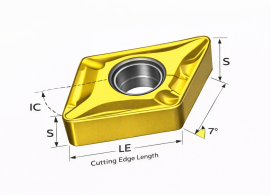
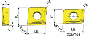
RE | IC | S | D1 |
|
ZCMT040104R-BM |
0.4 | 4.40 | 6.40 | 1.70 |
|
ZCMT040104L-BM |
0.4 | 4.40 | 6.40 | 1.70 |
|
ZCMT050204-BM |
0.4 | 5.60 | 5.60 | 2.10 |
|
ZCMT060204-BM |
0.4 | 6.40 | 6.40 | 2.38 |
|
ZCMT070304-BM |
0.4 | 7.50 | 7.50 | 3.18 |
| ZCMT080304-BM | 0.4 | 8.40 | 8.40 |
3.18 |
| ZCMT10T304-BM | 0.4 | 10.50 | 10.50 |
3.97 |
| ZCMT10T308-BM | 0.8 | 10.50 | 10.50 |
3.97 |
| ZCMT130404-BM | 0.4 | 13.40 | 13.40 |
4.76 |
| ZCMT130408-BM | 0.8 | 13.40 | 13.40 |
4.76 |
| ZCMT170508-BM | 0.8 | 17.40 | 17.40 |
5.56 |


Reviews
There are no reviews yet.